Home > Tech Gallery > Technical Feast | A Brief Analysis of MMU Waterline Settings in RDMA Network

Time: October 12th, 2024


RDMA (Remote Direct Memory Access) has been widely used in data centers, especially in AI, HPC, big data, and other scenarios, due to its high performance and low latency advantages. To ensure the stable operation of RDMA, the basic network needs to provide end-to-end lossless zero packet loss and ultra-low latency capabilities, which has also led to the deployment of network flow control technologies such as PFC and ECN in RDMA networks. In RDMA networks, setting the MMU (Memory Management Unit) waterline appropriately is crucial for ensuring losslessness and low latency. This article will explore RDMA networks and analyze various strategies for configuring the MMU waterline based on real-world deployment experiences.
What is RDMA?
RDMA (Remote Direct Memory Access), commonly known as remote DMA technology, is created to solve the delay in server-side data processing during network transmission.
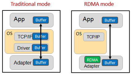
▲Figure 1 Comparison of working mechanisms between traditional mode and RDMA mode
As shown in the figure above, in the traditional mode, the process of transmitting data between applications on two servers is as follows:
●
First, the data must be copied from the application cache to the TCP protocol stack cache in the kernel;
● Then copy it to the driver layer;
● Finally, copy it to the network card cache.
Multiple memory copies necessitate repeated CPU intervention, leading to significant processing delays of up to tens of microseconds. Additionally, the CPU's heavy involvement in this process consumes substantial performance resources, which can adversely affect normal data computations.
In RDMA mode, application data can bypass the kernel protocol stack and write directly to the network card. The significant benefits include:
● The processing delay is reduced from tens of microseconds to less than 1 microsecond.
● The whole process requires almost no CPU involvement, saving performance.
● The transmission bandwidth is higher.
RDMA’s demands on the network
RDMA is increasingly utilized in high-performance computing, big data analysis, high I/O concurrency, and other scenarios. Application software such as iSCSI, SAN, Ceph, MPI, Hadoop, Spark, TensorFlow, and others have started to implement RDMA technology. For the underlying network that supports end-to-end transmission, low latency (in the microsecond range) and losslessness are the most critical indicators.
Low latency
Network forwarding delay mainly occurs at the device node (optical transmission delay and data serial delay are ignored here). Device forwarding delay includes the following three parts:
● Store-and-forward latency: chip forwarding pipeline processing delay, each hop will generate a chip processing delay of about 1 microsecond (the industry has also tried to use the cut-through mode, and the single-hop delay can be reduced to about 0.3 microseconds).
● Buffer cache latency: When the network is congested, packets are cached and wait to be forwarded. In RDMA networks, larger buffers are generally beneficial, but a reasonable buffer size is still required.
● Retransmission latency: In the RDMA network, other technologies are used to ensure that packets are not lost, so this part will not be analyzed.
Lossless
RDMA can transmit at full rate in a lossless state; however, once packet loss and retransmission occur, performance can drop sharply. In traditional network modes, the primary method to achieve no packet loss is through the use of large buffers. However, as mentioned earlier, this approach conflicts with the goal of low latency. Therefore, in an RDMA network environment, the objective is to achieve no packet loss while using smaller buffers.
Under this restriction, RDMA achieves losslessness mainly by relying on network flow control technology based on PFC and ECN.
Key technologies of RDMA lossless network: PFC
PFC (Priority-based Flow Control) is a queue-based backpressure mechanism that prevents buffer overflow and packet loss by sending Pause frames to notify the upstream device to pause packet transmission.
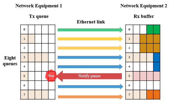
▲Figure 2 Schematic diagram of PFC working mechanism
PFC allows you to suspend and restart any of the virtual channels individually without affecting the traffic of other virtual channels. As shown in the figure above, when the buffer consumption of queue 5 reaches the set PFC flow control waterline, PFC back pressure will be triggered:
● The local switch triggers a PFC Pause frame and sends it back to the upstream device.
● Upstream device receives the Pause frame, will pause sending messages in the queue and cache the messages in the Buffer.
● If the buffer of the upstream device also reaches the threshold, Pause frames will continue to be triggered to exert back pressure on the upstream device.
● Finally, data packet loss is avoided by reducing the sending rate of the priority queue.
● When the buffer occupancy drops to the recovery waterline, a PFC release message is sent.
Key technologies of RDMA lossless network: ECN
ECN (Explicit Congestion Notification): Explicit Congestion Notification is a relatively old technology that was not widely used until recently. This protocol mechanism operates between hosts.
ECN activates when a message encounters congestion at the egress port of a network device, triggering the ECN watermark. The ECN field in the IP header is then used to mark the data packet, indicating that it has encountered network congestion. Once the receiving server detects the ECN marking, it generates a Congestion Notification Message (CNP) and sends it to the source server. The CNP contains information about the flow that causes congestion. Upon receiving this notification, the source server reduces the corresponding flow-sending rate to alleviate congestion at the network device, thereby avoiding packet loss.
From the preceding description, we can understand that PFC and ECN can achieve zero packet loss in the end-to-end network by setting different watermarks. The reasonable setting of these watermarks is the refined management of the switch MMU, which is the management of the switch buffer. Next, we will analyze the PFC watermark setting in detail.
PFC waterline setting
Switch chips all have fixed pipelines (forwarding pipelines), and buffer management is in the middle of the in-chip and out-chip processes. When a message is at this position, the ingress and egress information of the message is already known, so logically the buffer can be managed separately in the ingress and egress directions.
The PFC waterline is triggered based on the ingress buffer management. The chip provides 8 queues in the ingress direction. We can map service packets of different priorities to different queues, thereby providing different buffer allocation solutions for packets of different priorities.

▲Figure 3 Components of a queue buffer
For each queue, the buffer allocation is designed into three parts according to the usage scenario: guaranteed cache, shared cache, and headroom.
Guaranteed cache: A dedicated cache for each queue ensures that each queue has a certain amount of cache to ensure basic forwarding;
Shared cache: This is the cache that can be requested when traffic bursts occur, and is shared by all queues.
Headroom: The cache that can continue to be used after the PFC waterline is triggered and before the server response slows down.
Ensure cache settings
A guaranteed cache is a static waterline (fixed and exclusive). The utilization of static waterlines is very low, but the resource consumption is very large. In actual deployment, we recommend not allocating the guaranteed cache to reduce the consumption of this part of the cache. In this way, the incoming message directly uses the shared cache space, which can improve the utilization of the buffer.
Shared Cache Settings
For the shared cache settings, a more flexible dynamic waterline is required. The dynamic waterline can determine whether resources can continue to be applied based on the current idle Buffer resources and the number of Buffer resources used by the current queue. Since the idle shared Buffer resources and the used Buffer resources in the system are constantly changing, the threshold is also constantly changing. Compared with the static waterline, the dynamic waterline can use the Buffer more flexibly and effectively and avoid unnecessary waste.
Ruijie Network switches support the dynamic allocation of buffer resources. The shared buffer settings are divided into 11 levels. The dynamic waterline alpha value = available queue buffer / remaining shared buffer. The larger the queue's alpha value, the higher its percentage of available shared buffer.
|
Hardware value of α
|
Maximum available percentage = α/ α+1
|
|
1/128
|
0.77
|
|
1/64
|
1.53
|
|
1/32
|
3.03
|
|
1/16
|
5.88
|
|
1/8
|
11.11
|
|
1/4
|
20.00
|
|
1/2
|
33.33
|
|
1
|
50.00
|
|
2
|
66.66
|
|
4
|
80.00
|
|
8
|
88.88
|
▲Table 1 the corresponding relationship between the shared waterline α value and the availability rate
Let's analyze it:
A smaller queue value of α is set, the smaller the maximum share of the shared cache that can be applied for. When the port is congested, PFC flow control will be triggered earlier. After PFC flow control takes effect, the queue speed will be reduced, which can effectively ensure that the network does not lose packets.
However, from a performance perspective, triggering PFC flow control too early will cause a decrease in RDMA network throughput. Therefore, we need to select a balanced value when setting the MMU waterline.
The PFC waterline is a very complex issue, and there is no fixed value in theory. In actual deployment, we need to analyze the business model in detail and build a test environment to optimize the waterline and find the best waterline that matches the business.
Headroom Settings
Headroom: As the name implies, it is the headroom used to cache queue messages from the time PFC is triggered to the time PFC takes effect. How large is the appropriate headroom setting? This is related to four factors:
● PG detects the triggering of the XOFF watermark when constructing and sending the PFC frame (this is mainly related to the configured detection accuracy and average queue algorithm, and fixed configuration is a fixed value).
● When the upstream receives the PFC Pause frame to when the queue forwarding stops (mainly related to the chip processing performance, the switching chip is a fixed value).
● PFC Pause frame transmission time on the link (proportional to the AOC cable/fiber distance).
● The transmission time of the message in the link after the queue stops sending (proportional to the AOC cable/fiber distance).
Therefore, we can calculate the cache size required by the headroom based on the network architecture and traffic model. With 100 meters of optical fiber + 100G optical module, caching 64-byte packets, the required headroom size is calculated to be 408 cells ( cell is the smallest unit of cache management, and a message will occupy one or more cells ), which is consistent with the actual test data. Of course, considering a certain redundancy, the headroom setting is recommended to be slightly larger than the theoretical value.
Practical Implementation of RDMA Network
Ruijie Networks has built an RDMA network that simulates real services in its R&D center. The architecture is as follows:

▲Figure 4 Ruijie Networks RDMA networking architecture
● Networking model: large core three-level networking architecture, with high-density 100G line cards used in the core;
● In the POD: The spine uses a BOX device that provides 64 100G interfaces, and the leaf uses a BOX device that provides 48 25G interfaces + 8 100G interfaces;
● Leaf acts as a server gateway and supports PFC-based flow control between servers (identifying the DSCP of packets and performing PG mapping), as well as congestion ECN marking.
● RDMA only runs inside the POD. There is no cross-POD RDMA traffic, so the core does not need to be aware of RDMA traffic.
● To avoid packet loss due to congestion. PFC flow control technology needs to be deployed between Leaf and Spine. Spine devices also need to support congestion-based ECN marking.
● Leaf and Spine devices support PFC flow control frame statistics, ECN marking statistics, congestion packet loss statistics, queue-based congestion statistics, etc., and support synchronizing statistical information to a remote gRPC server through gRPC.
Final Thoughts
Ruijie Networks has established an immersion networking environment in its R&D center that simulates real business scenarios, utilizing equipment such as the RG-S6510, RG-S6520, RG-N18000-X series 25G/100G network equipment, large testers, and 25G servers. After conducting extensive immersion tests with multiple business models, we have developed recommended experience values for the MMU watermark settings in RDMA networks.
However, there are still challenges in deploying RDMA networks, including issues such as PFC storms, deadlock problems, and the complexities of designing ECN watermarks in multi-level networks. Ruijie Networks has also conducted research and gathered insights on these challenges.
Summary
Remote Direct Memory Access (RDMA) technology has transformed data transfer in data centers, particularly in high-performance computing (HPC) and big data environments, by significantly reducing latency and enhancing throughput. To maintain RDMA's performance advantages, the underlying network must achieve lossless transmission and ultra-low latency, requiring effective flow control mechanisms such as Priority Flow Control (PFC) and Explicit Congestion Notification (ECN). A critical aspect of achieving these goals is the proper configuration of the Memory Management Unit (MMU) waterline settings, which directly influence the network's ability to handle data efficiently without packet loss. This article will analyze deployment experiences to provide insights into optimal MMU waterline configurations, ensuring the stability and performance of RDMA networks.

Related Blog:
Exploration of Data Center Automated Operation and Maintenance Technology: Zero Configuration of Switches
Technology Feast | How to De-Stack Data Center Network Architecture
Technology Feast | A Brief Discussion on 100G Optical Modules in Data Centers
Research on the Application of Equal Cost Multi-Path (ECMP) Technology in Data Center Networks
Technology Feast | How to build a lossless network for RDMA
Technology Feast | Distributed VXLAN Implementation Solution Based on EVPN
Exploration of Data Center Automated Operation and Maintenance Technology: NETCONF
Featured blogs
- Ruijie RALB Technology: Revolutionizing Data Center Network Congestion with Advanced Load Balancing
- CXL 3.0: Solving New Memory Problems in Data Centres (Part 2)
- Multi-Tenant Isolation Technology in AIGC Networks—Data Security and Performance Stability
- Multi-dimensional Comparison and Analysis of AIGC Network Card Dual Uplink Technical Architecture
- A Brief Discussion on the Technical Advantages of the LPO Module in the AIGC Computing Power Network